BGA Solder Best Practices: A Comprehensive Guide to BGA, Rework, and Troubleshooting
Introduction to BGA Soldering
Ball Grid Array (BGA) soldering is revolutionizing the design and production of printed circuit boards (PCBs). This BGA article covers all aspects, from the basics related to the array of solder balls underneath BGAs, to best practices to achieve reliable solder joints, to advanced quality control methodologies. Since BGA solder joints are not visible, adequate inspection and process control methodologies are necessary to obtain the highest quality solder joint in advanced circuit board designs of today.
What Is a BGA Package?
Structure of Ball Grid Array Packages
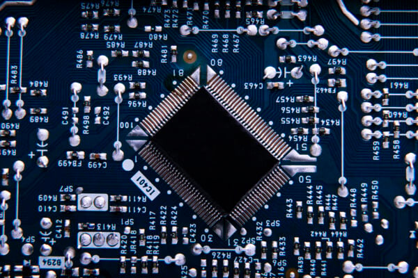
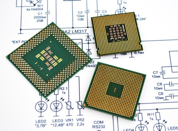
A Ball Grid Array (BGA) package is an advanced type of IC package whose leads are in the form of an array of solder balls at the bottom instead of traditional leads. This allows for a large number of connections in a small area on the printed circuit board (PCB). Every solder joint is vital since these little solder balls are where they make all of their electrical connections to the PCB.
In a BGA, the solder balls are on the bottom of the package and connect to corresponding pads on the PCB. These connections provide high-density integration, low resistance and high performance. As a result of the design, solder joints lie beneath the package, preventing direct visual inspection and making X-ray inspection equipment more important for quality control.
Elements of a typical BGA:
| Feature | Description |
| Array of Solder Balls | Grid pattern, number varies (100+ typical) |
| Substrate | Circuit carrier (ceramic/PCB) |
| Silicon Die | The IC chip, connected to substrate |
| Underfill (optional) | Epoxy for added mechanical strength |
Why BGAs Are Widely Used in Modern Electronics
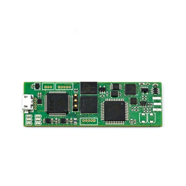
- Space Efficiency: BGAs maximize the number of connections per unit area, enabling miniaturization of the printed circuit assemblies.
- Reliable Solder Joints: The spherical nature of the solder balls in BGA packages enables self-centering in reflow, which results in consistent and dependable joints.
- Superior Electrical and Thermal Performance: Signal integrity and heat dissipation are greatly enhanced with the shorter paths between die and PCB.
BGA vs. Other SMT Types
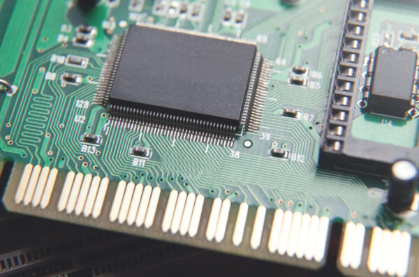
BGA packages vary from QFP and QFN in that they have a matrix of solder balls rather than rows of pins, thereby enabling higher density and performance. Since all BGA solder joints are buried and the traditional visual inspection is not possible, every BGA solder joint is subjected to more rigorous examination.
| Package Type | Solder Attachment | Inspection Method | Applications |
| BGA | Array of solder balls | X-ray, Electrical Testing | CPUs, FPGAs, High-end ASICs |
| QFP/QFN | Peripheral leads/pads | Visual, AOI | Microcontrollers, Analog ICs |
Typical Uses and Limitations
Typical Applications:
- High-speed processors, memory modules, networking ICs
Limitations:
- Visual inspection is impossible; requires X-ray inspection equipment
- Demands exacting control of soldering temperature and paste
- Specialized tools (such as a dedicated BGA rework station) are needed for repairs
Core Tools and Equipment for BGA Soldering
The BGA soldering requires a accuracy advanced tools to get reliable joints and keep the quality of the BGA installation:
- Reflow Oven: You can monitor soldering temperature profile, which is important in making uniform joints.
- Hot Air or Infrared BGA Rework Station: Allows the removal and replacement of BGAs without affecting nearby components on the PCB.
- Solder Paste Stencil and Squeegee: Applies the right quantities of solder paste, which is essential to avoid either too little or too much amounts of solder, both of which can cause unreliable solder joints.
- Microscope: It is necessary for inspection of stencil printing and BGA positioning as solder joints are concealed.
- X-ray Inspection Equipment: That is the only way to look at every BGA solder joint and be sure that none are incomplete and not detected.
Tip: Use ESD-safe tools and BGA/PCB components should be stored in humidity controlled containers to prevent latent defects and oxidation.
Pre-Soldering Preparation
Adequate pre-soldering BGA and PCB assembly preparations are the basis for predictable outcomes.
PCB and Pad Preparation
- Cleanliness: Remove contaminants and oxidation from printed circuit board pads.
- Moisture Control: Bake out BGAs and PCBs according to their MSL classification to prevent “popcorning” defects.
- Pad Design: Refer to IPC-7095 and the manufacturer recommendations for pad shape and soldermask opening.
Solder Paste & Stencil Printing
- Stencil Thickness: Select a stencil that provides a good balance between allowing sufficient and not excessive amount of solder – which is critical since too much solder paste can result into bridging cracks, and too little solder volume into incomplete solder joints.
- Aperture Design: Apertures are to be laser-cut to accommodate the array of solder balls so that the deposits are uniform.
- Paste Handling: Store and handle the solder paste by the instructions of the manufacturers to protect its properties.
Environmental Controls
Maintain the assembly room environment temperature and humidity within an appropriate range to avoid printing and reflow problems. Dry too, and solder paste harcicles; humid too, and flux activation may be compromised.
Step-by-Step BGA Soldering Process
1. PCB Preparation
Clean the pads on the printed circuit and bake the board if required. Make sure all materials are in date and moisture sensitive for quality BGA and PCB assembly.
2. Solder Paste Printing
Apply solder paste with a laser cut stencil and be careful on the amount of solder paste on each pad. Check under the scope for uniform shape and coverage.
3. Component Placement
Use a pick and place machine or manual alignment to place the BGA. Make sure the BGA solder ball array is lined up with the PCB pads. Reflow self alignment is useful; but more accurate placement results in better results.
4. Reflow Soldering
Perform a finely adjusted soldering temperature curve in reflow oven. The correct temperature ramp, temperature peak and temperature cooling are important for each BGA soldering joint to be fully reflowed and to prevent widely seen BGA solder joint defects such as head-in-pillow and voiding.
5. Cooling and Cleaning
Let the board cool gradually to prevent microcracking or pad cratering. Remove any flux residues that may be detrimental to the quality of the solder joints in the long run.
6. Inspection and Quality Control
Perform X-ray to determine the quality of the solder joint since you can’t directly visually inspect it. Look for good solder joints, no bridging, cold solder joints, or voids.
Summary Table: Step-by-Step BGA Soldering Process
| Step | Key Action | Equipment |
| Prep | Clean PCB, check moisture and oxidation | PCB cleaner, oven |
| Paste | Accurate application of solder paste | Stencil, squeegee |
| Placement | Align solder balls to PCB pads | Pick-and-place, microscope |
| Reflow | Correct soldering temperature profile | Reflow oven |
| Cooling | Gradual, controlled cooling of the circuit board | Reflow oven, ambient environment |
| Cleaning | Remove flux residue for long-term joint quality | PCB cleaner, ultrasonic cleaner |
| Inspection | X-ray and electrical/functional tests—since BGA solder joints are hidden, visual inspection is impossible | X-ray inspection equipment, testing stations |
Common Defects & How to Avoid Them
BGA soldering has its challenges since all of the solder joints lie under the balls of solder. To know these defects and to know how to prevent them is the secret to produce reliable printed circuit board assemblies.
Common BGA Soldering Defects
Voiding
- Description:Air pockets, flux or gas trapped in the solder joint.
- Impact:Reduces mechanical strength and thermal/electrical conductivity.
- Prevention:Control the reflow temperature profile, use the right amount of solder paste, and select a high-quality paste.
Head-in-Pillow (HIP)
- Description:The BGA solder balls and the PCB pad ones are melting but not merging, causing partial solder joints.
- Impact:Intermittent or open connections that maybe be manifest only under thermal or mechanical loading.
- Prevention:Moisture baking, component warpage minimization, and use a proven soldering temperature profile.
Solder Bridging
- Description:Excess solder creates a connection between adjacent solder balls, causing short circuits under the package.
- Impact:Short circuits, immediate board failure.
- Prevention:Designing a good stencil, controlling the amount of solder paste, and accurate placement.
Misalignment
- Description:The component moves during reflow, so not all solder balls touch their corresponding PCB pads.
- Impact:Open connections, potential for latent failures.
- Prevention:Use accurate pick-and-place tools, check alignment under a microscope, and do not vibrate during reflow.
Pad Cratering and Open/Weak Joints
- Description:Cracking or delamination beneath PCB pads, often resulting from thermal or mechanical stress at rework stations.
- Impact:Reduced reliability, leading to potential early field failure.
- Prevention:Limited rework cycles, minimal use of dedicated BGA rework station and selecting a robust PCB laminate.
Inspection Methods for BGA Soldering
Because BGA solder joints are not visible, advanced inspection techniques are necessary for QC in every modern BGA and PCB assembly.
X-ray Inspection Equipment
- Primary Method:A must for every assembly house, X-ray shows solder quality, voids, bridging, misalignments and full or missing solder balls in the ball array.
- X-ray Analysis:Allows measurement/percentage of voids per joint, checks all solder balls on the BGA, and contributes to production process development.
Visual and Functional Testing
- Visual Inspection:This can be done for the case and for any adjacent components. But since all the vital connections are buried inside the BGA, that is not enough by itself.
- Electrical Testing:Checks continuity but can fail to detect subtle issues such as voids or weak/marginal connections unless used in conjunction with X-ray results.
Dye-and-Pry and Ball Shape Analysis
- Dye-and-Pry:Used in failure analysis by introducing dye and then removing the package to check if the dye penetrates any fractures or incomplete solder joints.
- Ball Shape Analysis:X-ray or cross-sectioning to evaluate the collapse and the shape of each solder ball.
BGA Rework & Reballing
Importance of a Dedicated BGA Rework Station
When defects are found, a dedicated BGA rework station is necessary for the removal and replacement of the defective BGA. This is selective local heating, safe package removal and reflowing of replacement devices without harm to adjacent components on the pcb.
Reballing Process for Reliable Solder Joints
Reballing involves removing and replacing all the solder balls on a BGA, with the use of a stencil and a precisely controlled heat source to reball the joint quality.Key for success:
- Accurate alignment during reballing
- Consistent soldering temperature and profile
- Quality control checksusing X-ray to ensure reliable BGA joints are restored
BGA Soldering vs Other SMT Soldering Methods
- BGA and PCB Assembly Complexity:BGA soldering is more sensitive to the temperature profile, paste deposition, and inspection, as all solder joints are concealed.
- QFP/QFN:Simple for visual inspection, but with lower I/O pin density and usually weaker mechanical connections.
- BGA Design and Assembly Advantages:Higher density, better performance of advanced printed circuits, but with more complex quality control methods.
Advanced Tips & Best Practices for Reliable BGA Soldering
- Profile Optimization:Adjust the ovens periodically and check the boards with thermocouples to confirm the correct soldering temperature profile is applied to all circuit board assemblies.
- Moisture Sensitivity:Always observe MSL ratings and bake components as recommended to avoid problems such as head-in-pillow.
- Documentation:Employ the all‑inclusive BGA soldering and inspection guide as your SOP to aid in the standardization of training and reduction of process variation.
- Solder Paste:Use and storage of the mfr approved solder paste will ensure you see the best practice / best performance for stable and reliable solder joints.
- Process Validation:Compare x-ray images from different batches on a regular basis in order to detect the trends and the operator or equipment problems at the early stages and keep the long-term quality of the BGA assembly.
Professional PCB Assembly and BGA Services
Many companies rely on professional assembly providers for critical jobs involving BGA and PCB technology. These vendors offer:
- High-end X-ray inspection equipment for every BGA solder joint
- Experienced operators using dedicated BGA rework stations
- Statistical process control (SPC) to continuously verify solder quality and joint quality
- For prototype to high-volume runs, services that leverage automated feedback loops to detect and respond to recurrence of issues
Frequently Asked Questions about BGA Soldering
Q:Why is visual inspection impossible for BGAs?
A:Since BGA solder joints are located under the package, a direct visual inspection with a microscope or camera is not possible, unless x-rays or destructive techniques are employed.
Q:How can I ensure reliable solder joints in BGAs?
A:Through the control of how much solder paste is applied on the PCB, the optimization of the soldering temperature profile, and an X-ray inspection of each production batch.
Q:What are the common BGA soldering defects to watch for?
A:Voiding, head-in-pillow, bridging, opens, incomplete solder joints, and pad cratering can be eliminated by implementing proper process control and using the right equipment.
Q:Do I need a dedicated BGA rework station for repair?
A:Yes, the safe removal or replacement of the PCB or adjacent parts without harm to the PCB or around components requires localized heat and control.
Q:What’s the best way to monitor the quality of BGA and PCB assemblies?
A:Use a combination of X-ray inspection, electrical testing, statistical defect logging, and process documentation as outlined in your guide to BGA best practices.
Conclusion
BGA soldering is an extremely accurate process of pcb assembly that depends on tightly controlled paste printing, reflow temperature profiling and inspection techniques. Because all of the solder joints are concealed under the package, x-ray inspection and process stability are critical for ensuring long-term reliability.
If the process is controlled well and rework procedures are optimized, typical defects such as voiding, head-in-pillow, bridging, etc. can be reduced to a minimum level and the product performance can be stably maintained in high density electronics application.
At LingKey, we offer PCB assembly and BGA soldering services with the support of SMT production, X-ray inspection, engineering DFM services for both prototype and volume production, enabling customers to have stable manufacturing quality and dependable delivery.


