How to Read SMD Capacitor Markings and Polarity
Introduction
In the current density PCB production, SMD (Surface Mount Device) accounts for the majority of electronic components. Capacitors are also very important in all present day products and more so are of the SMD variety. But, with the miniaturization of the components, so is the marking system, and SMD codes can be a little bit mysterious. Learning to identify SMD capacitors and read their capacitor value and polarity is essential for troubleshooting, avoiding damage, and more importantly, reliability. This application note describes all commonly used coding system for SMD, ceramic, film, tantalum and electrolytic capacitor so that you can approach confidently in circuit board assembling, PCB pad breakdown and rework.

Why Reading Capacitor Markings Correctly is Critical on a PCB
Getting capacitor selection and orientation wrong can spell disaster:
- Choosing the Wrong Capacitance and Voltage: For instance, substituting a 0.1 μF decoupling capacitor for the required 10 μF on the power rail of the microcontroller might let noise that causes the system to randomly reset.
- Misreading Polarity Marks: Reverse a tantalum SMD capacitor and it will usually pop or short out during circuit operation.
- Incorrect DC Voltage Rating: Inadequate DC voltage withstand will lead to early failure, especially in power circuits and car designs.
- Component Sourcing and PCB Assembly Delays: Misunderstandings of the labeling system result in the procurement of the incorrect part and slow down the production runs.
- Quality Inspections: Errors might not be detected until the board bring-up or QA phase, at which point rework is expensive and time-consuming.
Capacitor Schematic Symbols Explained
Knowing schematic symbols is crucial if you’re going to be reading electrical drawings, pinouts, and BOMs. This is especially the case for SMDs where the marking system may be not existing and orientation on the PCB pad is critical.
| Capacitor Type | Schematic Symbol | Example Use | Tip for Assembly |
| Non-polarized (ceramic) | Two parallel equal-length vertical lines | Decoupling, highfrequency filtering, general-purpose circuits | No positive/negative polarity; can be mounted in any direction. |
| Polarized (tantalum, electrolytic) | Parallel lines with a “+” marking for positive terminal | Power supply energy storage, lowfrequency filtering | Strict polarity required. Positive terminal must connect to higher voltage; reverse connection causes failure. |
| Variable | Capacitor symbol with an angled arrow overlay | RF tuning, frequency adjustment circuits | Adjust capacitance by rotating the mechanical trimmer. |
Note: On a PCB, check that symbol and silkscreen align—wrong silkscreen is a frequent cause of SMD assembly errors!
How to Read Capacitor Markings on Through-Hole Capacitors
Through-hole capacitors are typically larger and have more room for printing but they can feature any of the code systems — European, EIA or with the actual value printed.
Electrolytic Capacitors
- Marking Example: “47μF 16V”
- Polarity: The negative end is marked with a long stripe on the body, which has to be aligned to the negative pad on the PCB.
- Caution: Some vintage capacitors use “MFD” for microfarads (µF).
Film Capacitors
- Marking Example: “4n7” (4.7 nF) or “330K” (33 x 10^4 pF = 330,000 pF)
- Tolerance Code: Common codes include J (±5%), K (±10%), M (±20%).
Ceramic Capacitors
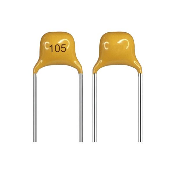
EIA 3-Digit Code and Examples
| Code | Value (pF) | Value (nF) | Value (µF) |
| 104 | 100,000 | 100 | 0.1 |
| 105 | 1,000,000 | 1,000 | 1 |
| 472 | 4,700 | 4.7 | 0.0047 |
| 683 | 68,000 | 68 | 0.068 |
Tolerance and Voltage Ratings on Through-Hole Parts
- Tolerance: e.g., “K” = ±10%
- Voltage: e.g., “50V” often printed directly on the body
Advanced Markings: Codes, Tolerance, Voltage, and Temperature
Codes can seem intimidating, but they’re systematic. Understand each:
- 3-digit EIA codes: For example, “104” = 0.1 μF (see table above).
- Voltage ratings: Letter codes (e.g., “A” for 10V, “C” for 16V) are common in SMD tantalum.
- Tolerance Letters:
- F: ±1%
- G: ±2%
- J: ±5%
- K: ±10%
- M: ±20%
- Z: +80% / −20%
- Temperature Coefficient Codes: Identify the dielectric and its stability.
- C0G/NP0 (Class I): ±30ppm/°C, ultra-stable.
- X7R (Class II): ±15%, moderate stability.
- Y5V, Z5U: Least stable, suited for general purpose.
Tip: RF, timing and precision circuits prefer C0G/NP0. Bulk decoupling is performed with X7R or X5R due to their high volumetric efficiency.
SMD Capacitor Package Sizes and Their Implications
Today’s circuit board layouts push for the tiniest package (e.g. 0201 or 0402 for MLCCs), but when size is reduced, the voltage and capacitance ratings might also drop—always look at the datasheet.
| SMD Package | Metric | DC Voltage Range | Typical Application |
| 0201 | 0603 | 6.3V–16V | Mobile, RF |
| 0402 | 1005 | 10V–50V | Decoupling, filtering |
| 0603 | 1608 | 16V–100V+ | General purpose, power |
| 0805/1206 | 2012/3216 | 16V–100V+ | Automotive, bulk filtering |
Pro Advice: For high capacitance and voltage, use a larger package or parallel multiple SMD MLCC to share the load and reduce DC bias derating.
Common SMD Capacitor Dielectric Types and Their Applications
| Dielectric | Temperature Range | Stability | Common Uses |
| C0G (NP0) | −55°C to +125°C | Very high | RF, timing, oscillators |
| X7R | −55°C to +125°C | Moderate | Decoupling, filtering |
| X5R, X8R | Wider temps, less stable | Good | Power, bulk capacitance |
| Y5V, Z5U | −30°C to +85°C | Low | General purpose, lowest cost |
| Polyester (PET) | −55°C to +125°C | Good | Coupling, audio, timing |
| Polypropylene (PP) | −55°C to +105°C | Excellent | Precision, high-frequency |
| Tantalum | −55°C to +125°C | Good | High efficiency, bulk, timing |
| Aluminum Electrolytic | −40°C to +105°C | Moderate | Bulk capacitance, power supply |
Tip: Ceramic and film capacitors are applicable in various fields, but your dielectric selection should always be based on the stability required, temperature rating, and size limitations. For example, X7R is excellent for decoupling and C0G/NP0 is the best for RF and high-precision filters.
Useful Resources for Decoding Capacitor Markings
When reading any capacitor becomes confusing, lean on the following tools and strategies:
- Official Manufacturer Codebooks:Each leading brand (Murata, TDK, Kemet, Vishay, Panasonic) releases the marking system information guides and application notes.
- PCB Assembly Documentation:The BOM sheets, pick-and-place files and silkscreen on your PCB will help you verify the correct component is placed on the correct pad.
- Online Calculators and Apps:Digi-Key’s Capacitor Code Calculator or Murata Codes are online tools that also allow you to convert quickly.
- LCR Meter/Multimeter:For unmarked SMDs, in particular MLCCs, measurement in circuit or on the bench is frequently the only method to verify the actual capacitance and voltage.
- Community Forums, Stack Exchange & EEVblog:Great for troubleshooting odd ball codes or old reel inventory you can’t identify.
SMD Capacitor Codes: Identification, Markings, and Polarity
Visual Identification — SMD Types
- MLCC (Multilayer Ceramic):Don’t Care Usually Unmarked, Mostly Rectangular, Many sizes (From 0201 to 1812). Use the placement on a PCB circuit board or BOM for identification, measure to
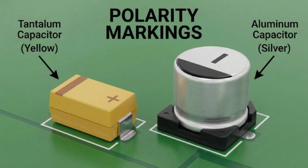
- Tantalum SMD/Chip:Generally yellow or black, labeled with 3 digit value code (e.g. 106 means 10 μF), voltage letter code (e.g. “C” = 16V), tolerance and a polarity stripe on the body (positive electrode).
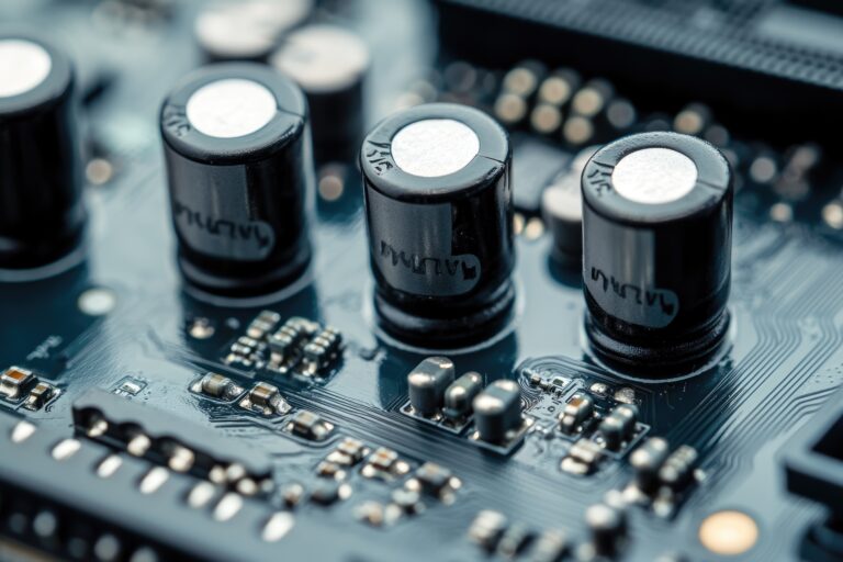
- Aluminum Electrolytic SMD (V-chip):Barrel/can type, usually with a shaded or striped ring to indicate the negative lead, with capacitance and voltage rated sometimes printed on the top.
SMD Marking System Breakdown
- Capacitance Value
- “106” means 10 × 10⁶ pF = 10 μF.
- Voltage Rating(Tantalum/Aluminum types)
- Letter indicates voltage (A = 10V, C = 16V, etc.).
- Tolerance Code
- “J” = ±5%, “K” = ±10%, “M” = ±20%, “Z” = +80%/−20%.
- Polarity Marking
- Stripe on the body for tantalum = positive electrode.
- Stripe or shaded base for aluminum SMD = negative terminal.
- SMD LED Polarity
- Stripe, triangle, or line—polarity is important for the correct lighting, more so on boards full of SMD LEDs.
Example Table: SMD Tantalum Capacitor Codes
| Marking | Capacitance | Voltage | Tolerance | Stripe | Meaning |
| 106C | 10μF | 16V | ±20% | Yes | Positive terminal marked |
| 227A | 220μF | 10V | ±10% | Yes | High-efficiency, bulk |
Troubleshooting SMD Capacitor Identification Problems
Identifying capacitors is not always easy, especially when the markings have worn off, for unmarked SMD types or when the component is on a assembled PCB. Common problems and solutions:
- Unmarked MLCCs:Check component location, compare with BOM, or measure with an LCR meter.
- Worn or Partially Missing Codes:Cross-reference physical size, pad size, and surrounding circuit context.
- Sourcing Problems:In part sourcing and PCB assembly, always state “value+voltage+tolerance+dielectric” in the BOM.
- Polarity Confusion:Terminals are important in tantalum and aluminum SMD capacitors. The body has a stripe to indicate positive (tantalum) or negative (aluminum electrolytic). Match these up with the corresponding pads on the PCB.
Understanding SMD Polarity: Capacitor, LED, Diode, Inductor, & IC
Polarity for Other SMD Components
- SMD LEDs:Polarity marking (stripe, triangle ), always indicates the cathode (−); orientation is critical for output—if you get it backwards you get no light and possibly damage.
- Diodes:Similar to SMD LEDs—stripe for cathode.
- Inductors:Most are non-polar, but shielded power inductors may use a dot or bar for pin 1.
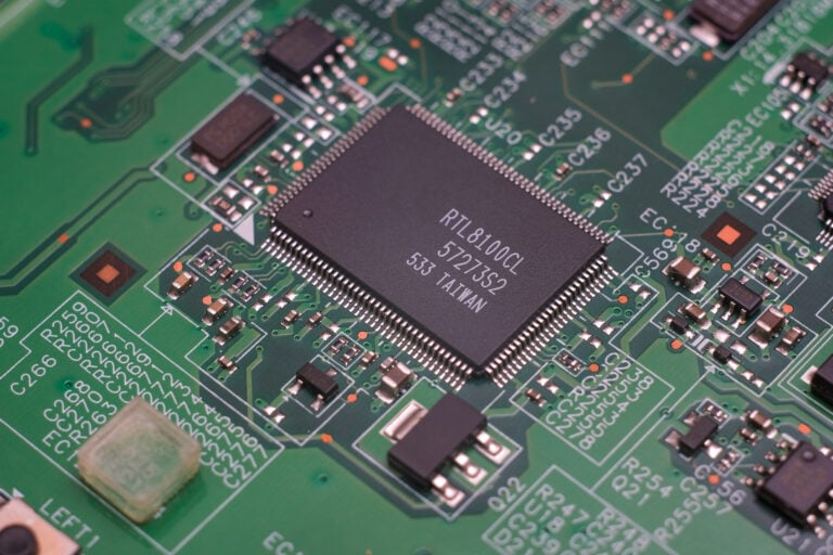
- ICs:Notch or dot for pin 1. This is important for IC programming – wrong orientation may damage the IC and sometimes the board!
- Power Supply Modules:Clearly marked input/output—never guess polarity.
Best Practices
- Refer to the assembly drawing and check the orientation of the Polarity Stripe of every SMD before Reflow soldering or manual rework.
- In tight spaces or on high-speed boards use a microscope or magnifying glass to view small markings and pad layouts.
- In high-reliability sectors (automotive, aerospace) a double check of marking system and assembly is
Frequently Asked Questions
Q:How do I identify SMD capacitors with no markings?
A:Consult your BOM, your component sourcing records, and the assembly drawing for the correct part. For additional check, measure capacitance with a multimeter or LCR meter.
Q:Why are SMD capacitor codes sometimes missing or partially printed?
A:For tiny packages (0402, 0201) there is just no space to print. Sometimes the ink will be rubbed off in the reflow soldering; always check the circuit board documentation.
Q:Can choosing the wrong SMD capacitor type or orientation damage my project?
A:Yes. Applying wrong capacitance/voltage or reversing polarity on a tantalum/aluminum electrolytic type SMD usually causes destruction of the component, more often at power-up.
Q:What is the best way to confirm capacitor value and voltage when in doubt?
A:Use a multimeter or LCR meter. For further information (like DC leakage and ESR), see the part’s datasheet.
Q:Do SMD LEDs require specific SMD pad layouts for correct polarity?
A:Yes.Pads must be aligned to the SMD LED’s cathode and anode side for the LED to work correctly and so as not to cause reverse current during test.
Q:What should I do if ceramic and film capacitor codes can seem ambiguous?
A:Refer to the datasheet, crosscheck with the standard code tables, verify the packaging size and if required, measure it physically.
Conclusion
Decoding SMD capacitors codes, polarity indication, package size and type of dielectric is necessary to know for making SMD capacitor assembly, sourcing and long term reliability of the circuit. Correct identification enables engineers to avoid polarity failures, incorrect capacitance selection and expensive rework in production and testing.
With the PCB designs trending smaller and denser in layout, component handling and inspection become more critical. From unmarked MLCCs and polarized tantalum capacitors to SMD marking interpretation translates into smoother assembly processes and more stable electronic performance.
On the LingKey official website, we offer professional PCB manufacturing and PCB assembly service for consumer electronics, industrial control, automotive, and communication products. With advanced SMT lines, AOI inspection, X-ray test and rich engineering experience, LingKey enable customer to get high reliable PCB and high quality electronic assembly for prototype and mass production project.